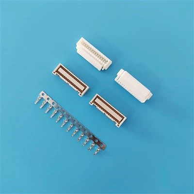

2.50mm Pitch Connectors Manufacturer & Supplier
We manufacture 2.50mm pitch connectors and cable assemblies for electronic equipment manufacturers, OEMs, and contract manufacturers. Available product types include wire-to-board connectors, PCB headers, female sockets, crimp terminal housings, and custom wire harnesses.
Depending on the selected series, buyers can specify circuit count, mounting style, wire gauge, contact plating, housing material, and cable assembly requirements. For replacement projects, we evaluate the original part number, mating interface, PCB footprint, and electrical requirements before confirming compatibility.
-
![Substitute IL-G-2P-S3T2-SA,IL-G-3P-S3T2-SA,IL-G-4P-S3T2-SA,IL-G-5P-S3T2-SA,IL-G-6P-S3T2-SA,IL-G-7P-S3T2-SA,IL-G-8P-S3T2-SA,IL-G-9P-S3T2-SA,IL-G-10P-S3T2-SA,IL-G-11P-S3T2-SA,IL-G-12P-S3T2-SA,IL-G-13P-S3T2-SA,IL-G-14P-S3T2-SA,IL-G-15P-S3T2-SA,Housing Terminal Cable Wafer]() Substitute IL-G-2P-S3T2-SA,IL-G-3P-S3T2-SA,IL-G-4P-S3T2-SA,IL-G-5P-S3T2-SA,IL-G-6P-S3T2...Specifications:Rated current: 3A AC, DCRated voltage: 500V DCTemperature range: -40 deg C to +105 deg CContact resistance: 20m Omega Max.Insulation resistance: 1000M Omega Min.Withstand pressure:
-
![Substitute IL-G-2P-S3L2-SA,IL-G-3P-S3L2-SA,IL-G-4P-S3L2-SA,IL-G-5P-S3L2-SA,IL-G-6P-S3L2-SA,IL-G-7P-S3L2-SA,IL-G-8P-S3L2-SA,IL-G-9P-S3L2-SA,IL-G-10P-S3L2-SA,IL-G-11P-S3L2-SA,IL-G-12P-S3L2-SA,IL-G-13P-S3L2-SA,IL-G-14P-S3L2-SA,IL-G-15P-S3L2-SA,Housing Terminal Cable Wafer]() Substitute IL-G-2P-S3L2-SA,IL-G-3P-S3L2-SA,IL-G-4P-S3L2-SA,IL-G-5P-S3L2-SA,IL-G-6P-S3L2...Specifications:Rated current: 3A AC, DCRated voltage: 500V DCTemperature range: -40 deg C to +105 deg CContact resistance: 20m Omega Max.Insulation resistance: 1000M Omega Min.Withstand pressure:
-
![Replaces IL-G-2P-S3L2-SA,IL-G-3P-S3L2-SA,IL-G-4P-S3L2-SA,IL-G-5P-S3L2-SA,IL-G-6P-S3L2-SA,IL-G-7P-S3L2-SA,IL-G-8P-S3L2-SA,IL-G-9P-S3L2-SA,IL-G-10P-S3L2-SA,IL-G-11P-S3L2-SA,IL-G-12P-S3L2-SA,IL-G-13P-S3L2-SA,IL-G-14P-S3L2-SA,IL-G-15P-S3L2-SA,Housing Terminal Cable Wafer]() Replaces IL-G-2P-S3L2-SA,IL-G-3P-S3L2-SA,IL-G-4P-S3L2-SA,IL-G-5P-S3L2-SA,IL-G-6P-S3L2-S...Specifications:Rated current: 3A AC, DCRated voltage: 500V DCTemperature range: -40 deg C to +105 deg CContact resistance: 20m Omega Max.Insulation resistance: 1000M Omega Min.Withstand pressure:
-
![Replaces IL-G-2P-S3T2-SA,IL-G-3P-S3T2-SA,IL-G-4P-S3T2-SA,IL-G-5P-S3T2-SA,IL-G-6P-S3T2-SA,IL-G-7P-S3T2-SA,IL-G-8P-S3T2-SA,IL-G-9P-S3T2-SA,IL-G-10P-S3T2-SA,IL-G-11P-S3T2-SA,IL-G-12P-S3T2-SA,IL-G-13P-S3T2-SA,IL-G-14P-S3T2-SA,IL-G-15P-S3T2-SA,Housing Terminal Cable Wafer]() Replaces IL-G-2P-S3T2-SA,IL-G-3P-S3T2-SA,IL-G-4P-S3T2-SA,IL-G-5P-S3T2-SA,IL-G-6P-S3T2-S...Specifications:Rated current: 3A AC, DCRated voltage: 500V DCTemperature range: -40 deg C to +105 deg CContact resistance: 20m Omega Max.Insulation resistance: 1000M Omega Min.Withstand pressure:
-
![Substitute IL-G-2S-S3C2-SA,IL-G-3S-S3C2-SA,IL-G-4S-S3C2-SA,IL-G-5S-S3C2-SA,IL-G-6S-S3C2-SA,IL-G-7S-S3C2-SA,IL-G-8S-S3C2-SA,IL-G-9S-S3C2-SA,IL-G-10S-S3C2-SA,IL-G-11S-S3C2-SA,IL-G-12S-S3C2-SA,IL-G-13S-S3C2-SA,IL-G-14S-S3C2-SA,IL-G-15S-S3C2-SA,IL-M-C2-50,Housing Terminal Cable Wafer]() Substitute IL-G-2S-S3C2-SA,IL-G-3S-S3C2-SA,IL-G-4S-S3C2-SA,IL-G-5S-S3C2-SA,IL-G-6S-S3C2...Specifications:Rated current: 3A AC, DCRated voltage: 500V DCTemperature range: -40 deg C to +105 deg CContact resistance: 20m Omega Max.Insulation resistance: 1000M Omega Min.Withstand pressure:
-
![Replaces IL-G-2S-S3C2-SA,IL-G-3S-S3C2-SA,IL-G-4S-S3C2-SA,IL-G-5S-S3C2-SA,IL-G-6S-S3C2-SA,IL-G-7S-S3C2-SA,IL-G-8S-S3C2-SA,IL-G-9S-S3C2-SA,IL-G-10S-S3C2-SA,IL-G-11S-S3C2-SA,IL-G-12S-S3C2-SA,IL-G-13S-S3C2-SA,IL-G-14S-S3C2-SA,IL-G-15S-S3C2-SA,IL-M-C2-50,Housing Terminal Cable Wafer]() Replaces IL-G-2S-S3C2-SA,IL-G-3S-S3C2-SA,IL-G-4S-S3C2-SA,IL-G-5S-S3C2-SA,IL-G-6S-S3C2-S...Specifications:Rated current: 3A AC, DCRated voltage: 500V DCTemperature range: -40 deg C to +105 deg CContact resistance: 20m Omega Max.Insulation resistance: 1000M Omega Min.Withstand pressure:
-
![Alternative IL-G-2P-S3L2-SA,IL-G-3P-S3L2-SA,IL-G-4P-S3L2-SA,IL-G-5P-S3L2-SA,IL-G-6P-S3L2-SA,IL-G-7P-S3L2-SA,IL-G-8P-S3L2-SA,IL-G-9P-S3L2-SA,IL-G-10P-S3L2-SA,IL-G-11P-S3L2-SA,IL-G-12P-S3L2-SA,IL-G-13P-S3L2-SA,IL-G-14P-S3L2-SA,IL-G-15P-S3L2-SA,Housing Terminal Cable Wafer]() Alternative IL-G-2P-S3L2-SA,IL-G-3P-S3L2-SA,IL-G-4P-S3L2-SA,IL-G-5P-S3L2-SA,IL-G-6P-S3L...Specifications:Rated current: 3A AC, DCRated voltage: 500V DCTemperature range: -40 deg C to +105 deg CContact resistance: 20m Omega Max.Insulation resistance: 1000M Omega Min.Withstand pressure:
-
![Alternative IL-G-2P-S3T2-SA,IL-G-3P-S3T2-SA,IL-G-4P-S3T2-SA,IL-G-5P-S3T2-SA,IL-G-6P-S3T2-SA,IL-G-7P-S3T2-SA,IL-G-8P-S3T2-SA,IL-G-9P-S3T2-SA,IL-G-10P-S3T2-SA,IL-G-11P-S3T2-SA,IL-G-12P-S3T2-SA,IL-G-13P-S3T2-SA,IL-G-14P-S3T2-SA,IL-G-15P-S3T2-SA,Housing Terminal Cable Wafer]() Alternative IL-G-2P-S3T2-SA,IL-G-3P-S3T2-SA,IL-G-4P-S3T2-SA,IL-G-5P-S3T2-SA,IL-G-6P-S3T...Specifications:Rated current: 3A AC, DCRated voltage: 500V DCTemperature range: -40 deg C to +105 deg CContact resistance: 20m Omega Max.Insulation resistance: 1000M Omega Min.Withstand pressure:
-
![Alternative IL-G-2S-S3C2-SA,IL-G-3S-S3C2-SA,IL-G-4S-S3C2-SA,IL-G-5S-S3C2-SA,IL-G-6S-S3C2-SA,IL-G-7S-S3C2-SA,IL-G-8S-S3C2-SA,IL-G-9S-S3C2-SA,IL-G-10S-S3C2-SA,IL-G-11S-S3C2-SA,IL-G-12S-S3C2-SA,IL-G-13S-S3C2-SA,IL-G-14S-S3C2-SA,IL-G-15S-S3C2-SA,IL-M-C2-50,Housing Terminal Cable Wafer]() Alternative IL-G-2S-S3C2-SA,IL-G-3S-S3C2-SA,IL-G-4S-S3C2-SA,IL-G-5S-S3C2-SA,IL-G-6S-S3C...Specifications:Rated current: 3A AC, DCRated voltage: 500V DCTemperature range: -40 deg C to +105 deg CContact resistance: 20m Omega Max.Insulation resistance: 1000M Omega Min.Withstand pressure:
-
![Replaces 2JQ-BT,3JQ-BT,4JQ-BT,5JQ-BT,6JQ-BT,7JQ-BT,8JQ-BT,9JQ-BT,10JQ-BT,11JQ-BT,12JQ-BT,13JQ-BT,14JQ-BT,15JQ-BT,20JQ-BT,2JQ-ST,3JQ-BST,4JQ-ST,5JQ-ST,6JQ-ST,7JQ-ST,8JQ-ST,9JQ-ST,10JQ-ST,11JQ-ST,12JQ-ST,13JQ-ST,14JQ-ST,15JQ-ST,20JQ-BT,Housing Wafer Cable Terminal]() Replaces 2JQ-BT,3JQ-BT,4JQ-BT,5JQ-BT,6JQ-BT,7JQ-BT,8JQ-BT,9JQ-BT,10JQ-BT,11JQ-BT,12JQ-B...Specifications:Rated current: 3A AC, DCRated voltage: 250V DCTemperature range: -40 deg C to +105 deg CContact resistance: 20m Omega Max.Insulation resistance: 1000M Omega Min.Voltage: 1000V
-
![Replaces S2B-XH-A,S3B-XH-A,S4B-XH-A,S5B-XH-A,S6B-XH-A,S7B-XH-A,S8B-XH-A,S9B-XH-A,S10B-XH-A,S11B-XH-A,S12B-XH-A,S13B-XH-A,S14B-XH-A,S15B-XH-A,Housing Wafer Cable Terminal]() Replaces S2B-XH-A,S3B-XH-A,S4B-XH-A,S5B-XH-A,S6B-XH-A,S7B-XH-A,S8B-XH-A,S9B-XH-A,S10B-X...Specifications:Rated current: 3A AC, DCRated voltage: 250V DCTemperature range: -40 deg C to +105 deg CContact resistance: 20m Omega Max.Insulation resistance: 1000M Omega Min.Voltage: 1000V
-
![Replaces S2B-XH-SM4-TB,S3B-XH-SM4-TB,S4B-XH-SM4-TB,S5B-XH-SM4-TB,S6B-XH-SM4-TB,S7B-XH-SM4-TB,S8B-XH-SM4-TB,S9B-XH-SM4-TB,S10B-XH-SM4-TB,S11B-XH-SM4-TB,S12B-XH-SM4-TB,S13B-XH-SM4-TB,S14B-XH-SM4-TB,S15B-XH-SM4-TB,Housing Wafer Cable Terminal]() Replaces S2B-XH-SM4-TB,S3B-XH-SM4-TB,S4B-XH-SM4-TB,S5B-XH-SM4-TB,S6B-XH-SM4-TB,S7B-XH-S...Specifications:Rated current: 3A AC, DCRated voltage: 250V DCTemperature range: -40 deg C to +105 deg CContact resistance: 20m Omega Max.Insulation resistance: 1000M Omega Min.Voltage: 1000V


2.50mm Pitch Connector Series Options
|
Connector Type |
Mounting / Configuration |
Available Options |
Mating Interface |
|
Shrouded Wafers / Headers |
Through-hole or SMT, depending on series |
Straight or right-angle; circuit count varies by model |
Compatible crimp terminal housing |
|
Crimp Terminal Housings |
Cable-mounted, wire-to-board |
Selected single-row configurations; AWG 20–28 where supported |
Matching wafer or pin header |
|
Board-to-Board Pin Headers |
Through-hole or SMT, depending on design |
Single- or dual-row configurations; circuit count varies by series |
Compatible female socket |
|
Female Sockets / Receptacles |
Through-hole or SMT, depending on series |
Entry direction and circuit count depend on design |
Matching 2.50mm male header |
|
Board-In / Crimp Connectors |
Direct PCB connection or wire termination, depending on design |
Selected configurations for specific PCB and wire requirements |
Confirm by part number and drawing |
|
Custom Wire Harnesses |
Cable assembly based on approved specifications |
Wire length, wire type, pin assignment, and labeling options |
Specified connector pair |
Technical Specifications and Material Options
Electrical Performance
|
Parameter |
Proposed Specification |
Selection Notes |
|
Pitch |
2.50mm |
Confirm the actual mating pitch and dimensional drawing |
|
Rated Current |
3.0A to 5.0A AC/DC, depending on model |
Verify wire gauge, number of loaded circuits, temperature rise, and contact design |
|
Rated Voltage |
Up to 250V AC/DC, subject to model verification |
Confirm the applicable rating and safety requirements |
|
Initial Contact Resistance |
Proposed maximum: 10mΩ |
Confirm the measurement method and model-specific limit |
|
Post-Environmental Contact Resistance |
Proposed maximum: 20mΩ |
Confirm environmental conditioning and acceptance criteria |
|
Insulation Resistance |
Proposed minimum: 1,000MΩ at 500V DC |
Verify the specified test conditions |
|
Dielectric Withstanding Voltage |
Proposed value: 1,000V AC for 1 minute |
Confirm the rating for the selected connector series |
Mechanical and Material Parameters
|
Parameter |
Available / Proposed Options |
Selection Notes |
|
Insulator Material |
PA66 for selected through-hole designs; PA9T or LCP for selected SMT designs |
Confirm the exact resin grade and temperature rating |
|
Flammability Rating |
UL 94 V-0 where supported by the specified material |
Verify the material manufacturer's documentation and applicable component records |
|
Contact Base Metal |
Phosphor bronze or brass, depending on design |
Select according to contact geometry and electrical requirements |
|
Tin Plating |
Proposed thickness: 80–120 microinches over 50 microinches of nickel |
Confirm the plating stack and thickness measurement basis |
|
Gold Plating |
Proposed selective gold options: 1, 3, or 10 microinches over 50 microinches of nickel |
Confirm the available finish for the selected contact and application |
|
Operating Temperature |
Proposed ranges: -25°C to +85°C for selected standard designs; -40°C to +105°C for selected high-temperature designs |
Confirm the complete connector assembly's rated temperature range |
|
SMT Reflow |
Proposed peak temperature: 260°C for up to 10 seconds, where approved |
Verify the resin grade and manufacturer's soldering profile |
|
Wave Soldering |
Proposed condition: 245°C for up to 5 seconds, where applicable |
Confirm compatibility with the selected through-hole component and process |

Industrial Controls: Connections between control boards, relay modules, and internal wiring harnesses. Verify current requirements and vibration conditions for the intended equipment.
Home Appliances: Internal connections in HVAC equipment, washing machines, refrigerators, and other appliance electronics, subject to the product's electrical and safety requirements.
Automotive and Transportation Electronics: Potential use in auxiliary modules, HVAC controls, and telematics equipment. Confirm the required temperature range, vibration resistance, and automotive qualification requirements before selection.
Power Supplies and Energy Equipment: Connections within inverter controls, LED driver boards, and other electronic assemblies. Check circuit loading, insulation requirements, and thermal conditions.
Manufacturing Process and Quality Control
Our stated manufacturing process includes progressive die stamping, plastic injection molding, and automated pin insertion. Inspection and testing procedures should be defined according to the connector design and customer requirements.
[Raw Material IQC] --> [High-Speed Stamping & Molding] --> [Automated Pin Insertion]
[Shipment Inspection] <-- [Electrical and Mechanical Inspection] <-- [Dimensional and Visual Inspection]
In-House Testing Capabilities
The following are proposed inspection and testing items. Confirm which are available in-house and which are performed on every batch before publishing them as standard production controls.
|
Inspection / Test |
Purpose |
Records to Confirm |
|
Plating Thickness Analysis |
Verify gold or nickel plating thickness on specified contact areas |
XRF measurement records and acceptance limits |
|
Dimensional and Pin Alignment Inspection |
Check pitch, pin position, and coplanarity against the approved drawing |
Dimensional inspection report |
|
Electrical Continuity Testing |
Verify electrical connections and detect open circuits or incorrect connections |
Test procedure and production records |
|
Terminal Retention Testing |
Measure the force required to displace a terminal from its housing |
Test results and model-specific acceptance limits |
|
Solderability and Thermal Testing |
Evaluate soldering suitability and inspect for deformation or pin displacement under specified conditions |
Approved test profile and test report |
|
Wire Harness Inspection |
Verify pin assignment, continuity, crimp dimensions, and pull-out force where applicable |
Inspection records and approved work instructions |
OEM/ODM Customization and Wire Harness Assembly
Connector Customization
Pin Configuration: Selected pin lengths, straight or right-angle options, and approved missing-pin configurations.
Contact Finish: Tin or selective gold plating options for compatible series.
Housing Options: Available housing colors and keying configurations, depending on the product design.
Connector Cross-Reference: Technical evaluation of original part numbers, drawings, or samples for potential alternatives.
Custom Wire Harnesses
Wire harness requirements can be reviewed based on:
- Wire type and insulation specification, such as UL1007, UL1015, or UL1569 where applicable
- Wire gauge and finished wire length
- Connector part numbers and terminal compatibility
- Pin assignment and wiring schedule
- Crimp height and pull-out force requirements
- Labeling, heat-shrink tubing, and packaging requirements

Packaging, Lead Times

Lead Time
3–5 working days for standard sample delivery; 2–3 weeks for mass production volumes.

Packaging Formats
Tape & Reel with Kapton pick-up caps for automated SMT lines, Tube packaging, or Tray packaging for through-hole pins.

Documentation Support
3D STEP files, 2D CAD drawings, RoHS / REACH / UL compliance certificates, and IMDS documentation available upon request.
Our Factory

FAQ

Request a Quote for 2.50mm Pitch Connectors
To help us review the correct connector or wire harness, please provide the following information where available:
Connector type and circuit count
Original part number, drawing, or sample
Mounting style and PCB footprint
Rated current, voltage, and operating temperature
Wire gauge, wire length, and pin assignment for harnesses
Required contact plating and compliance documentation
Estimated order quantity, packaging requirements, and target delivery date
We're well-known as one of the most professional 2.50mm pitch suppliers in China. With abundant experience, we warmly welcome you to buy bulk advanced 2.50mm pitch made in China here from our factory. If you have any enquiry about cooperation, please feel free to email us.
Replaces XARR 02VF XARR 03VF XARR 04VF XARR 05VF XARR 06VF XARR 07VF XARR 08VF XARR 09VF XARR 10VF XARR 12VF XARR 14VF SXAM 001T P0 6 Housing Terminal Cable Wafer, Substitute 50 37 5023 50 37 5033 50 37 5043 50 37 5053 50 37 5063 50 37 5073 50 37 5083 50 37 5093 50 37 5103 50 37 5113 50 37 5123 50 37 5133 50 37 5143 50 37 5153 5263PBT Housing Terminal Cable Wafer, Substitute B08B XADSS N B10B XADSS N B12B XADSS N B14B XADSS N B16B XADSS N B18B XADSS N B20B XADSS N B22B XADSS N B24B XADSS N B26B XADSS N B28B XADSS N B30B XADSS N B32B XADSS N B34B XADSS N B36B XADSS N B38B XADSS N B40B XADSS N DIP WaferPopular Products