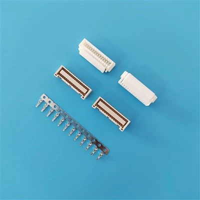

1.50mm Pitch Connectors Manufacturer & Supplier
We supply 1.50mm pitch connector systems for compact electronic assemblies requiring reliable wire-to-board connections. Our product range includes crimp housings, PCB headers and wafers, and female crimp terminals in SMT and through-hole configurations.
Available options include different circuit counts, header orientations, contact materials, plating finishes, and wire configurations. For OEM replacement projects, we support cross-reference evaluation using existing part numbers, drawings, PCB footprints, or physical samples. Mechanical and electrical compatibility should be verified against the selected target series before production approval.
- Pitch: 1.50mm
- Product Types: Crimp Housings, PCB Headers/Wafers, Female Crimp Terminals
- Circuit Range: 2–16 positions for applicable configurations
- Mounting Options: SMT and through-hole; vertical and right-angle headers
- Wire Range: AWG 24–30 for applicable terminal configurations
- Material Options: PA66, PA9T or LCP housings; brass or phosphor bronze contacts, subject to model availability
- Supply Options: Connector components, reel-packaged terminals and custom cable assemblies
-
![A1503(ZPD)alternative ZPD 1.50 Housing Terminal Wafer Cable]() A1503(ZPD)alternative ZPD 1.50 Housing Terminal Wafer CableSpecifications:Rated current: 1.5 to 2A AC, DCRated voltage: 100V DCTemperature range: -25 deg C to +105 deg CContact resistance: 30m Omega Max.Insulation resistance: 500M Omega Min.Voltage: 500V
-
![Replaces 503148-2670,Right-Angle,SMT Wafer]() Replaces 503148-2670,Right-Angle,SMT WaferSpecifications:Rated current: 2A AC, DCRated voltage: 100V DCTemperature range: -25 deg C to +105 deg CContact resistance: 20m Omega Max.Insulation resistance: 500M Omega Min.Voltage: 500V
-
![Replaces 503148-2470,Right-Angle,SMT Wafer]() Replaces 503148-2470,Right-Angle,SMT WaferSpecifications:Rated current: 2A AC, DCRated voltage: 100V DCTemperature range: -25 deg C to +105 deg CContact resistance: 20m Omega Max.Insulation resistance: 500M Omega Min.Voltage: 500V
-
![Replaces 503148-2270,Right-Angle,SMT Wafer]() Replaces 503148-2270,Right-Angle,SMT WaferSpecifications:Rated current: 2A AC, DCRated voltage: 100V DCTemperature range: -25 deg C to +105 deg CContact resistance: 20m Omega Max.Insulation resistance: 500M Omega Min.Voltage: 500V
-
![Replaces 503148-2070,Right-Angle,SMT Wafer]() Replaces 503148-2070,Right-Angle,SMT WaferSpecifications:Rated current: 2A AC, DCRated voltage: 100V DCTemperature range: -25 deg C to +105 deg CContact resistance: 20m Omega Max.Insulation resistance: 500M Omega Min.Voltage: 500V
-
![Replaces 503148-1870,Right-Angle,SMT Wafer]() Replaces 503148-1870,Right-Angle,SMT WaferSpecifications:Rated current: 2A AC, DCRated voltage: 100V DCTemperature range: -25 deg C to +105 deg CContact resistance: 20m Omega Max.Insulation resistance: 500M Omega Min.Voltage: 500V
-
![Replaces 503148-1670,Right-Angle,SMT Wafer]() Replaces 503148-1670,Right-Angle,SMT WaferSpecifications:Rated current: 2A AC, DCRated voltage: 100V DCTemperature range: -25 deg C to +105 deg CContact resistance: 20m Omega Max.Insulation resistance: 500M Omega Min.Voltage: 500V
-
![Replaces 503148-1470,Right-Angle,SMT Wafer]() Replaces 503148-1470,Right-Angle,SMT WaferSpecifications:Rated current: 2A AC, DCRated voltage: 100V DCTemperature range: -25 deg C to +105 deg CContact resistance: 20m Omega Max.Insulation resistance: 500M Omega Min.Voltage: 500V
-
![Replaces 503148-1270,Right-Angle,SMT Wafer]() Replaces 503148-1270,Right-Angle,SMT WaferSpecifications:Rated current: 2A AC, DCRated voltage: 100V DCTemperature range: -25 deg C to +105 deg CContact resistance: 20m Omega Max.Insulation resistance: 500M Omega Min.Voltage: 500V
-
![Replaces 503148-1070,Right-Angle,SMT Wafer]() Replaces 503148-1070,Right-Angle,SMT WaferSpecifications:Rated current: 2A AC, DCRated voltage: 100V DCTemperature range: -25 deg C to +105 deg CContact resistance: 20m Omega Max.Insulation resistance: 500M Omega Min.Voltage: 500V
-
![Replaces 503148-0870,Right-Angle,SMT Wafer]() Replaces 503148-0870,Right-Angle,SMT WaferSpecifications:Rated current: 2A AC, DCRated voltage: 100V DCTemperature range: -25 deg C to +105 deg CContact resistance: 20m Omega Max.Insulation resistance: 500M Omega Min.Voltage: 500V
-
![Alternatives 503148-4070,Right-Angle,SMT Wafer]() Alternatives 503148-4070,Right-Angle,SMT WaferSpecifications:Rated current: 2A AC, DCRated voltage: 100V DCTemperature range: -25 deg C to +105 deg CContact resistance: 20m Omega Max.Insulation resistance: 500M Omega Min.Voltage: 500V


Connector Series & Configurations
|
Component Type |
Mounting Style / Orientation |
Circuit Range / Wire Compatibility |
Key Features |
|
Crimp Housing |
Cable mount, single row |
2–16 positions for applicable models |
Polarized housing, friction-lock options and matching crimp terminals |
|
PCB Header / Wafer |
SMT or through-hole; vertical or right-angle |
2–16 positions for applicable models |
Brass or phosphor bronze contacts; tin or specified gold plating |
|
Female Crimp Terminal |
Wire crimp, continuous reel packaging where available |
AWG 24–30 for applicable terminal models |
Phosphor bronze options; pre-tinned or selective gold-plated finishes |
|
Custom Cable Assembly |
Single-ended leads, jumper wires or harnesses |
Wire gauge and length specified by project |
Custom pinouts, wire colors, lengths and jacket materials |
Technical Specifications & Configuration Options
Electrical Specifications
|
Parameter |
Proposed Specification |
Selection Considerations |
|
Rated Current |
1.0A for specified standard configurations; up to 2.5A for designated power-contact configurations |
Depends on terminal design, wire gauge, number of energized circuits, ambient temperature and allowable temperature rise |
|
Rated Voltage |
50V AC/DC standard reference; higher ratings require model-specific confirmation |
Confirm insulation design, clearances, creepage distances and applicable product rating |
|
Contact Resistance |
Proposed reference: ≤20mΩ initially; ≤30mΩ after specified environmental testing |
Confirm measurement method, test conditions and acceptance limits |
|
Insulation Resistance |
Proposed reference: ≥500MΩ at 500V DC |
Confirm the applicable model and test procedure |
|
Dielectric Withstanding Voltage |
Proposed reference: 500V AC for 1 minute |
Confirm the product rating and test requirements |
Mechanical & Environmental Specifications
|
Parameter |
Proposed Specification |
Selection Considerations |
|
Applicable Wire Gauge |
AWG 24, 26, 28 and 30 for compatible terminal models |
Confirm conductor construction and terminal compatibility |
|
Wire Insulation Outer Diameter |
0.80–1.20mm for applicable configurations |
Must match the selected terminal and insulation-barrel design |
|
Applicable PCB Thickness |
0.8–1.6mm, subject to header design |
Confirm the through-hole lead dimensions or SMT mounting requirements |
|
Operating Temperature |
Standard reference: -25°C to +85°C; selected high-temperature configurations may target -40°C to +105°C |
Depends on resin grade, contact plating, terminal design and assembly conditions |
|
SMT Pin Coplanarity |
Proposed reference: ≤0.10mm |
Confirm against the applicable drawing and inspection method |
|
Terminal Retention Force |
Proposed reference: ≥9.8N per terminal |
Confirm the housing-terminal combination and test conditions |
|
Mating Durability |
Proposed reference: 30 cycles for tin-plated contacts; 100+ cycles for selected gold-plated versions |
Confirm plating specification, mating conditions and validated test results |
Material & Plating Options
|
Component |
Material / Finish Options |
Verification Requirements |
|
Housing |
PA66, PA9T or LCP, depending on the series |
Confirm exact resin grade, operating temperature, color and flammability classification |
|
Housing Flammability |
UL 94 V-0 where applicable |
Verify the specific resin grade and supporting documentation |
|
Header Pins |
Brass or phosphor bronze |
Confirm the alloy and mechanical requirements for the selected model |
|
Header Pin Plating |
Matte tin over nickel or specified gold plating |
Confirm plating area, thickness and underplating requirements |
|
Female Terminals |
Phosphor bronze options |
Confirm the terminal part number and compatible housing |
|
Terminal Plating |
Pre-tinned or selective gold plating, subject to model availability |
Specify required plating thickness and contact area |

Industrial Controls & Robotics: Sensor connections, controller wiring, compact I/O boards and internal electronic assemblies.
LED Lighting & Display Modules: Power and signal connections for lighting drivers, display boards and control modules.
Smart Home & Appliances: Internal wiring for HVAC controls, smart meters and home automation equipment.
Medical Electronics: Connections within diagnostic monitors, portable instruments and other electronic assemblies, subject to applicable device requirements.
Automotive Electronics: Dashboard displays, ambient lighting and infotainment control modules where the selected components meet the project's automotive qualification requirements.
Manufacturing & Quality Control
Manufacturing Workflow
Raw Material Verification → Precision Stamping → Plastic Injection Molding → Component Assembly → Inspection & Testing → Packaging
Manufacturing Processes
- Precision Stamping: Progressive-die stamping for contact and terminal production. Critical dimensions and tolerances should be controlled against approved engineering drawings.
- Plastic Injection Molding: Housing production using the specified resin grade, with process controls intended to maintain dimensional consistency and terminal retention.
- Optical Inspection: CCD or other optical inspection methods may be used to check defined features such as pin position, terminal alignment and visible defects. Inspection coverage depends on the production line and product requirements.
- Terminal Crimping: Applicable cable assemblies can be evaluated through crimp dimensions, pull-force testing and, where required, crimp cross-section analysis.
Quality Verification Options
Depending on the actual production and quality-control scope, inspection plans may include:
- Dimensional inspection of housing, terminal and header features.
- Contact resistance, insulation resistance and dielectric withstand testing.
- Terminal retention and crimp pull-force testing.
- Crimp cross-section analysis for specified wire-terminal combinations.
- Solderability testing for relevant PCB-mount components.
- Plating-thickness verification using X-ray fluorescence (XRF), where available and specified.
- Environmental or corrosion testing when required by the product specification.
Drop-in Cross Reference: 100% mechanical and electrical pin-to-pin replacement for standard JST ZH and Molex 1.50mm series. Free sample kits available for PCB footprint verification and mating tests.
Custom Harness Assembly: Automated cut-strip-crimp production with custom wire lengths, jacket materials (PVC, Teflon, Silicone), specified pinouts, and custom color coding.
Packaging Formats:
- Headers/Wafers: Tape & Reel (TR) with pick-and-place caps for automated SMT line assembly, or Tube / Polybag options for DIP.
- Terminals: Continuous reel packaging (10,000 pcs/reel) compatible with automated terminal crimping applicators.
- Supply Chain Options: Standard Minimum Order Quantity (MOQ) starts from 1,000 pcs. Safety stock buffering and annual schedule contracts available for OEM partners.

Our Factory

FAQ

Information to Include in Your RFQ
To help us assess fit, compatibility and pricing, please provide:
Required circuit count and connector configuration.
Original part number, drawing, sample or PCB footprint, if available.
Wire gauge, insulation outer diameter and required cable length.
Current, voltage, operating temperature and environmental requirements.
Contact plating, compliance documentation and testing requirements.
Estimated annual demand, initial order quantity and target delivery schedule.
We're well-known as one of the most professional 1.50mm pitch suppliers in China. With abundant experience, we warmly welcome you to buy bulk advanced 1.50mm pitch made in China here from our factory. If you have any enquiry about cooperation, please feel free to email us.
Substitute ZPDR 12V S, Substitute 87439 1200, Substitute JST CZHR 08V SPopular Products